Export Results
Use this guide to export your optimized design from deFlex for downstream refinement in your CAD tool, structural analysis validation, or documentation.
Available exports
After a solver run completes, you can export:
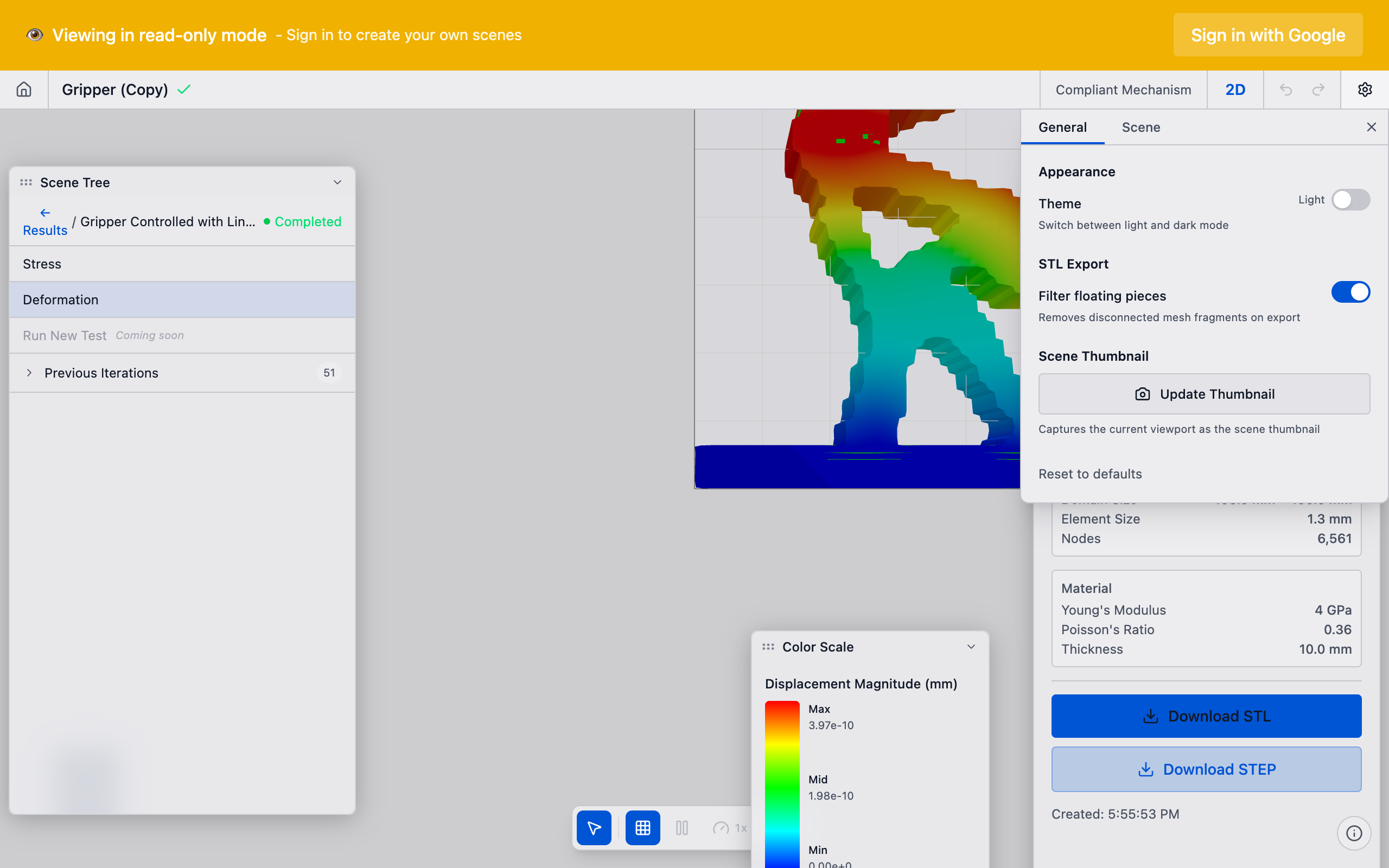
- Download STL -- the optimized mesh as a binary STL file for 3D printing, structural analysis, or CAD import. Optionally filters floating disconnected pieces (configurable in Settings).
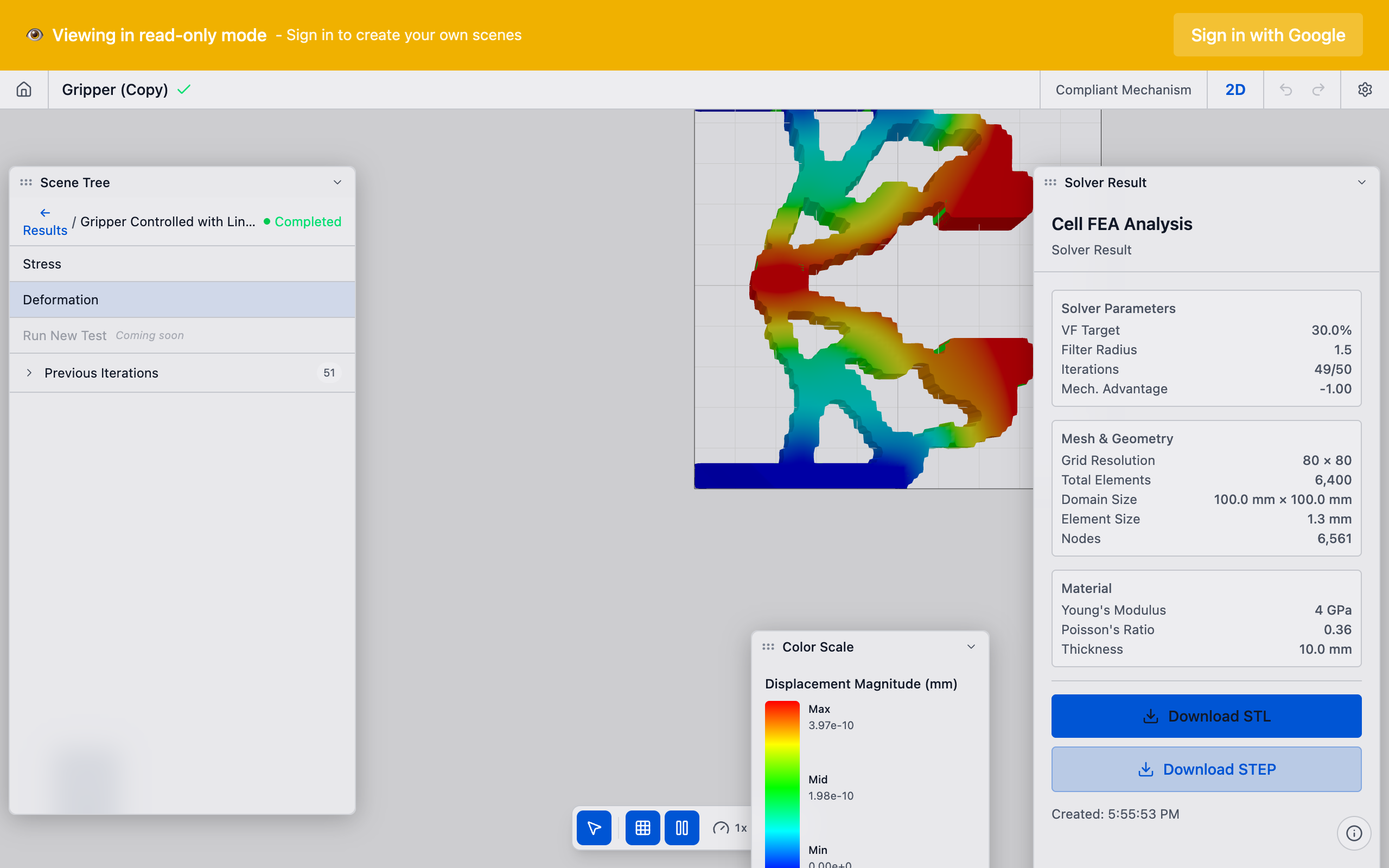
- Download STEP -- a CAD-native STEP (ISO 10303) solid generated server-side from the solver result. Ideal for direct import into SolidWorks, Fusion 360, or other parametric CAD tools.
- Export Demo Bundle (admin only) -- a set of files (STL mesh, displacement field, mesh nodes, and metadata JSON) used for landing-page interactive demos.
- Convergence Report -- an in-app modal displaying convergence plots and solver metrics.
- Topology image -- a screenshot or rendered image of the optimized topology for reports and presentations.
Steps
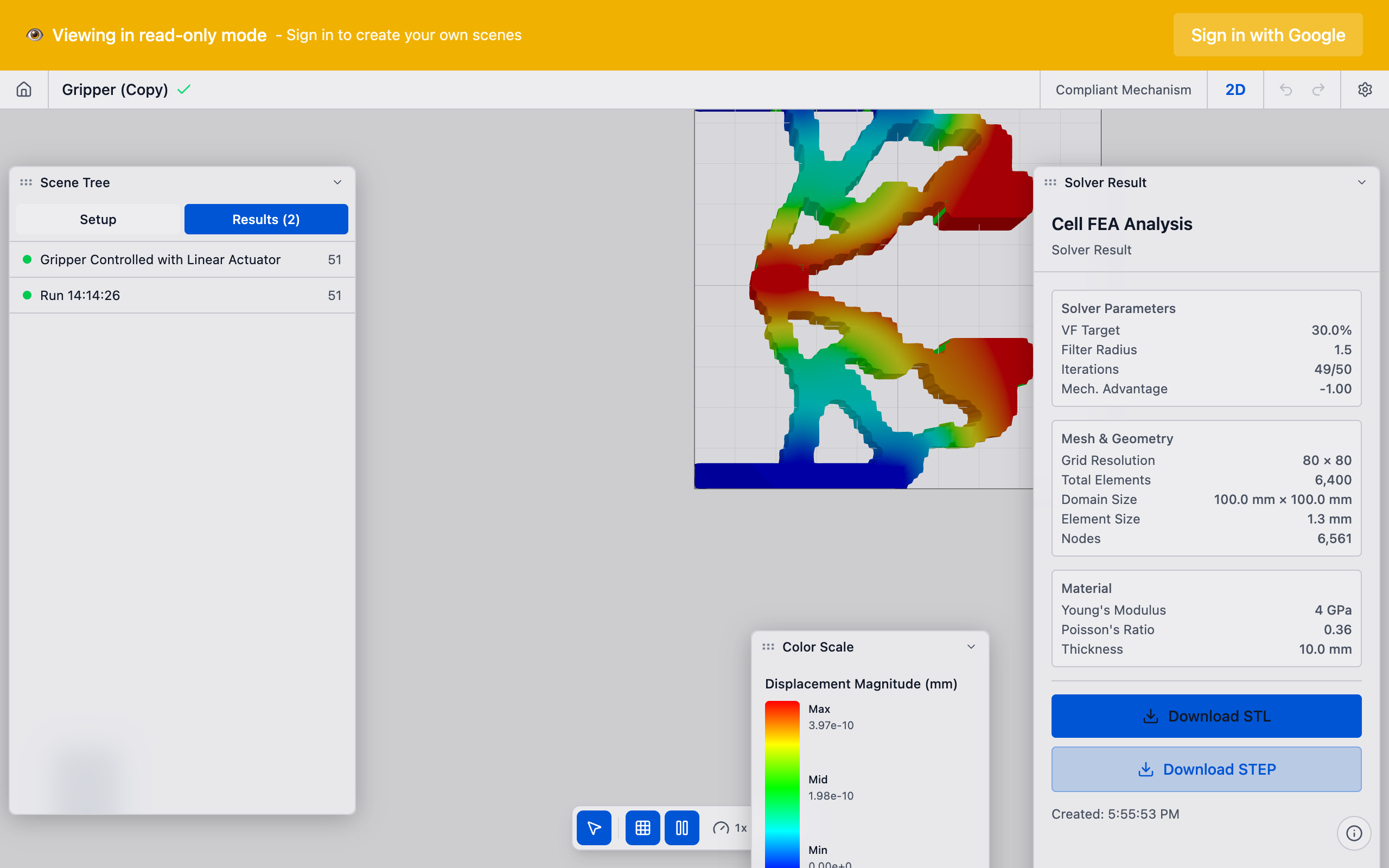
1. Select the solver run
In the Solver Runs section of the sidebar, click the run you want to export. If you have multiple runs, select the one with the best results.
2. Open the export options
In the solver run actions (the menu or buttons associated with the run card), look for export-related actions:
- Convergence Report: Opens an in-app modal with convergence plots (design performance, K_p, volume fraction, design change per iteration).
3. View the Convergence Report
Click Convergence Report on the solver run card. An in-app modal opens showing interactive charts:
- Design performance (compliance) vs. iteration
- Characteristic stiffness (K_p) vs. iteration
- Volume fraction vs. iteration
- Design change per iteration
The convergence report is an in-app viewer -- it is not a downloadable document. Use your browser's screenshot tool if you need to capture the charts for external sharing.
4. Download STL
Select a solver result in the scene tree, then click Download STL in the properties panel. The STL file is downloaded directly from the CDN. If the "Filter floating pieces" option is enabled in Settings, disconnected mesh fragments are automatically removed so you receive only the largest connected component.
5. Download STEP
Click Download STEP in the properties panel. This triggers a server-side conversion:
- A progress indicator shows "Generating STEP file..." while the backend converts the voxel mesh into a B-rep solid.
- Once generated, the browser downloads the
.stepfile automatically. - Import the STEP file directly into your CAD tool -- no manual tracing required.
If the conversion fails (e.g., the mesh is too complex), an error message appears in the properties panel.
Prefer STEP over STL when you need to edit the geometry in a parametric CAD tool. STEP files preserve solid topology, making it straightforward to add fillets, chamfers, and other features.
6. Download Demo Bundle (admin)
This export is only visible to admin users. Click Export Demo Bundle in the properties panel to download four files used for landing-page interactive demos:
{prefix}_mesh.stl-- the STL geometry{prefix}_displacement.bin-- Float32 nodal displacement field{prefix}_mesh_nodes.bin-- Float32 mesh node positions{prefix}_metadata.json-- grid dimensions, metrics, and settings
A progress callback reports the status of each individual file download.
7. Export for manual CAD refinement
If you prefer to manually refine the topology:
- Take the density field image or data as a reference overlay.
- In your CAD tool, sketch the topology boundary by tracing the solid regions.
- Smooth the jagged mesh edges into clean curves and splines.
- Add fillets to internal corners (the design optimization does not account for stress concentrations at sharp corners).
- Adjust wall thicknesses to meet manufacturing minimums.
Design optimization gives you the layout -- where material should and should not be. The final geometry requires engineering judgment to translate the pixel-level result into a smooth, manufacturable part.
8. Save the scene
Your scene, including all solver runs and their results, is automatically saved to the cloud. You can return to any scene from the home page and access previous runs at any time.
Tips
- Density threshold: When tracing the design in your CAD tool, use a density cutoff of 0.5 as the boundary between solid and void. Elements above 0.5 are solid; below 0.5 are void.
- Multiple runs: Export results from different parameter configurations to compare in a design review. The report includes all solver settings, making it easy to track what changed between runs.
- Screenshot shortcut: For quick sharing, use your browser's screenshot tool or the operating system screenshot function to capture the viewport. This is faster than generating a full report when you just need a visual reference.
- Sharing scenes: You can share the entire scene with a colleague who has a deFlex account. See Share a Scene for details.
What to do next
- Share your scene with collaborators
- Return to Interpret Results to compare multiple runs
- Start a new optimization by adjusting parameters and running again