Design Space
The design space (also called the design domain) is the region of your part where the optimizer is allowed to add or remove material. Everything outside this region is either void (empty space) or a preserve (forced solid). The design space is the optimizer's canvas — it defines the boundaries within which the solver searches for the optimal material distribution.
Why It Matters
The design space is the single most important input to the optimizer after preserve placement. A well-defined design space gives the solver room to discover efficient material layouts. A poorly defined one — too small, oddly shaped, or with preserves crammed into corners — constrains the solver and produces suboptimal or degenerate results.
Think of it this way: the solver can only place material where you allow it. If the optimal load path between your input and output preserves passes through a region you excluded from the design space, the solver cannot find that solution.
How It Works
From CAD Geometry to Design Domain
In deFlex, the design space is derived from your imported geometry:
- Import your part — a 2D cross-section or extruded plate (typically from a STEP file)
- The outer boundary of the part defines the maximum extent of the design domain
- Preserve regions are carved out — these areas are locked to density 1.0 (solid) and are not available for optimization
- Holes and cutouts in the geometry become void regions (density 0) that the optimizer cannot fill
- The remaining area is the design space — every element in this region gets a material value that the optimizer controls
Meshing the Design Space
The design space is discretized into a regular grid of mesh cells. Each cell is a small square (in 2D) with a single material value. The mesh resolution determines:
- Element count: total number of design values the optimizer controls
- Minimum feature size: the smallest structural member the optimizer can create (roughly 2-3 elements wide)
- Solve time: more elements means more computation per iteration
The mesh covers the entire bounding region — including preserve regions and voids. Preserve cells have their density locked to 1.0. Void cells (outside the part boundary or inside holes) have their density locked to 0. Only design space cells have free material values.
What Counts as Design Space
| Region | Density | Optimizer Controls? |
|---|---|---|
| Design space | 0 to 1 (free) | Yes |
| Preserve regions | 1 (locked solid) | No |
| Holes / cutouts | 0 (locked void) | No |
| Outside part boundary | 0 (locked void) | No |
Defining an Effective Design Space
Size and Proportions
The design space should be large enough to allow the optimizer to explore multiple load path options. As a guideline:
- Leave at least 2-3x the preserve diameter between preserves and the design space boundary
- Aspect ratios between 1:1 and 3:1 work well; very elongated domains (beyond 5:1) can produce degenerate solutions
- Symmetry in the design space does not guarantee symmetry in the result unless you apply symmetry constraints explicitly
If you are unsure about the right design space size, start larger. The volume fraction constraint ensures the optimizer does not fill the entire space. A design space that is "too large" wastes some computation but does not compromise the result. A design space that is "too small" can prevent the optimizer from finding good solutions.
Preserve Placement Within the Domain
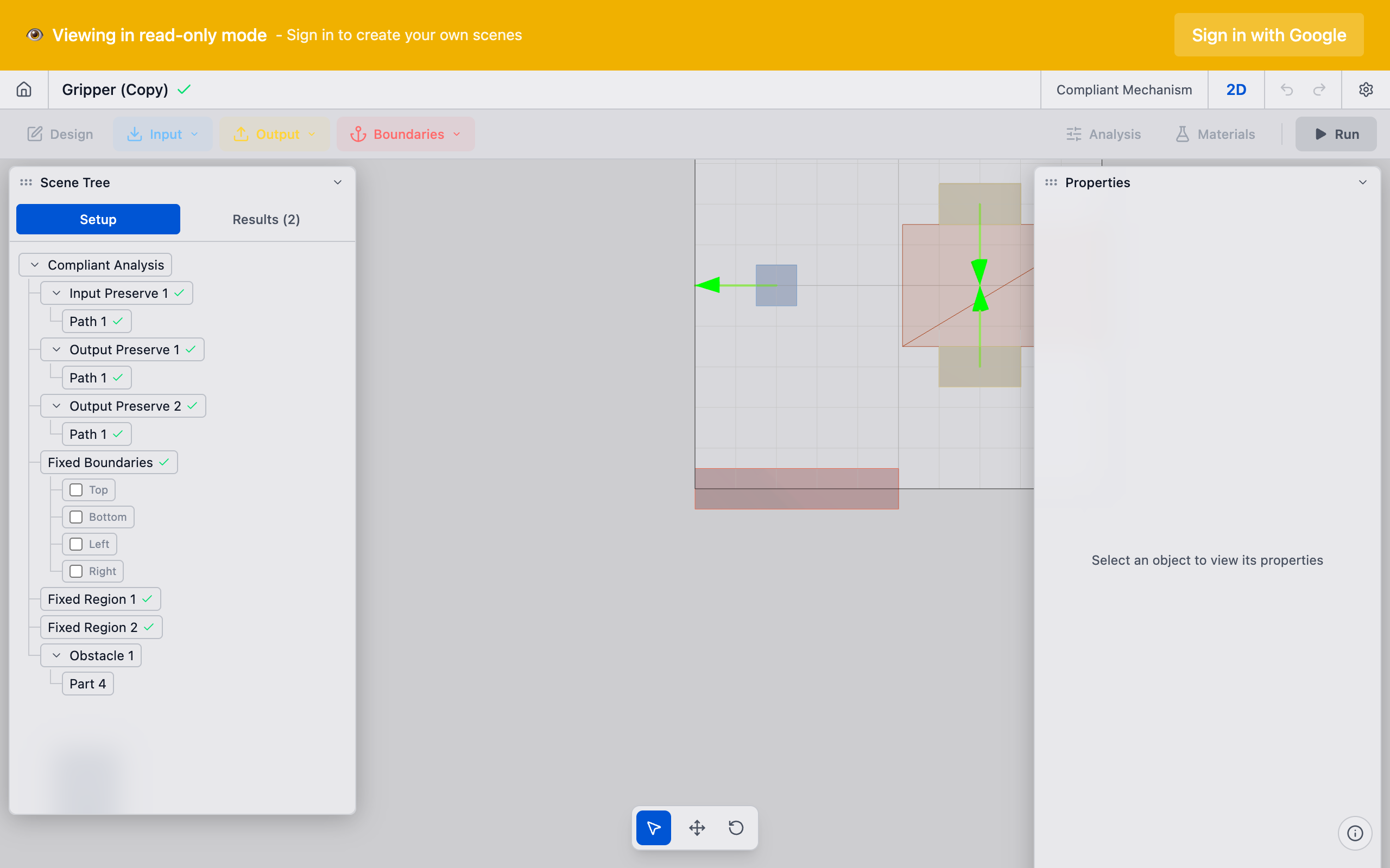
Where you place your preserves relative to the design space boundaries significantly affects the result:
- Corner preserves limit the optimizer's access to material on two sides — the mechanism can only connect through the available quadrants
- Edge preserves limit access on one side — the mechanism develops on the open side
- Interior preserves give the optimizer maximum flexibility — material can approach from all directions
- Closely spaced preserves create short, direct load paths — the optimizer has little room for creative topologies
- Widely spaced preserves allow longer, more complex load paths with potential for motion amplification
Common Pitfalls
Design space too small: the optimizer is forced into a direct, overly constrained connection between preserves. The result looks like a simple beam rather than an optimized mechanism.
Preserves too close to boundaries: the optimizer cannot route material around the preserves effectively. Move preserves inward or extend the design space.
Irregular geometry with narrow passages: thin corridors in the design space create bottlenecks. The optimizer must route all load paths through these narrow regions, which can produce stress concentrations.
Forgot to include necessary void regions: if your part has holes or cutouts that must remain empty (e.g., for clearance), make sure they are modeled in the geometry. The optimizer will happily fill them otherwise.
Technical Details
Mesh Cells
deFlex uses a regular grid of mesh cells for the 2D design optimization. Each cell has:
- 4 nodes at its corners
- 2 degrees of freedom per node (horizontal and vertical displacement)
- 1 material value that the optimizer controls
- Structural properties computed from the material value
Boundary Conditions on the Design Space
The design space boundary is free by default — there are no constraints on displacement at the edges. All boundary conditions come from the preserve system:
- Fixed preserves apply zero-displacement constraints at their nodes
- Input preserves apply force loads at their nodes in the specified direction
- Output preserves define the objective — maximize displacement at these nodes in the specified direction
If no fixed preserves are defined, the structural model is incomplete and the solver cannot proceed. Every problem needs at least one fixed preserve to be well-posed.
Passive Elements
Some cells in the design domain may be designated as passive — their density is fixed and cannot change during optimization. This includes:
- Preserve cells (passive solid, density = 1): guaranteed to remain in the final design
- Void cells (passive void, density = 0): guaranteed to remain empty
- All other cells are active and participate in the optimization
The ratio of active to total cells determines the actual size of the optimization problem. A design space with many preserves or voids has fewer active variables and solves faster.
Relationship to Mesh Resolution
The design space and mesh resolution are closely linked. See Mesh and Resolution for detailed guidance on choosing the right resolution for your design space. In brief:
- A 100x100mm design space at 1mm resolution = 10,000 elements
- The same space at 0.5mm resolution = 40,000 elements
- Solve time roughly scales as O(n^1.5) with element count
For initial exploration, use a coarse mesh (1-2mm elements) to get results in seconds. Once you find a promising setup, increase resolution for the final design.
See Also
- Design Optimization — the solver that operates on the design space
- Preserves Overview — the regions carved out of (or locked within) the design space
- Mesh and Resolution — discretizing the design space into mesh cells
- Volume Fraction — how much of the design space can be filled