Preserves Overview
Preserves are regions within the design space that the topology optimizer must keep solid. They are the mechanism's interface with the outside world — the places where forces are applied, where motion is measured, and where the part is bolted down. Without preserves, the optimizer has no boundary conditions and cannot produce a meaningful design.
Why It Matters
The preserve system is how you communicate your engineering intent to the solver. Every compliant mechanism needs:
- Somewhere for force to enter (input preserves)
- Somewhere for motion to come out (output preserves)
- Somewhere to anchor the mechanism (fixed preserves)
The relative positions, sizes, and directions of these preserves define the design problem more than any other parameter. Two identical design spaces with different preserve layouts will produce completely different mechanisms.
The term "preserve" comes from the idea that these regions are preserved (kept solid) during optimization. While the optimizer freely adds and removes material throughout the design space, preserve regions always remain at full density (density = 1).
Preserve Taxonomy
deFlex recognizes four types of preserves, each serving a distinct mechanical role:
| Type | Role | Has Direction? | Boundary Condition |
|---|---|---|---|
| Input Preserve | Force application point | Yes | Applied force |
| Output Preserve | Desired motion location | Yes | Design objective target |
| Fixed Preserve | Anchored mounting point | No | Zero displacement |
| Bolt Pad | Mounting location (rectangular) | Depends on role | Depends on role |
Preserve Subtypes
In addition to the four main preserve types, deFlex uses specialized subtypes for advanced workflows:
- deformation_function: defines a prescribed deformation pattern applied to a preserve region
- deformation_step: a STEP-file-based output deformation preserve where the user uploads undeformed and deformed STEP files and selects faces; the solver computes per-node displacement vectors from the face correspondence
- flexure_io: a combined input/output preserve used in the flexure solver's "combined" preserve mode, where a single preserve serves both roles
- fixed_boundary: a fixed preserve subtype representing edge-based boundary conditions (e.g., fixing an entire edge of the design space rather than a discrete region)
These subtypes are handled internally by the solver during parameter extraction and do not need to be configured manually in most workflows.
How They Work Together
A minimal compliant mechanism problem requires at least:
- 1 input preserve — where force enters
- 1 output preserve — where motion is desired
- 1 fixed preserve — where the mechanism is anchored
The solver uses these to construct the analysis problem:
- Fixed preserves contribute displacement boundary conditions (nodes are constrained to zero displacement)
- Input preserves contribute force boundary conditions (nodes receive applied loads in the specified direction)
- Output preserves define the design objective (maximize displacement at these nodes in the specified direction)
- All preserves have their density locked to 1.0, ensuring they remain solid in the final design
The Chain of Force
In every compliant mechanism, force follows a chain:
Input Preserve (force applied)
    |
    v
Design Space (topology optimizer distributes material here)
    |
    v
Output Preserve (desired motion occurs)
    |
    v
Fixed Preserve (reaction forces absorbed)
The optimizer's job is to fill in the middle — the material distribution in the design space that best transmits force from input to output while using the fixed preserves as anchoring points.
Defining Preserves in deFlex
Placement
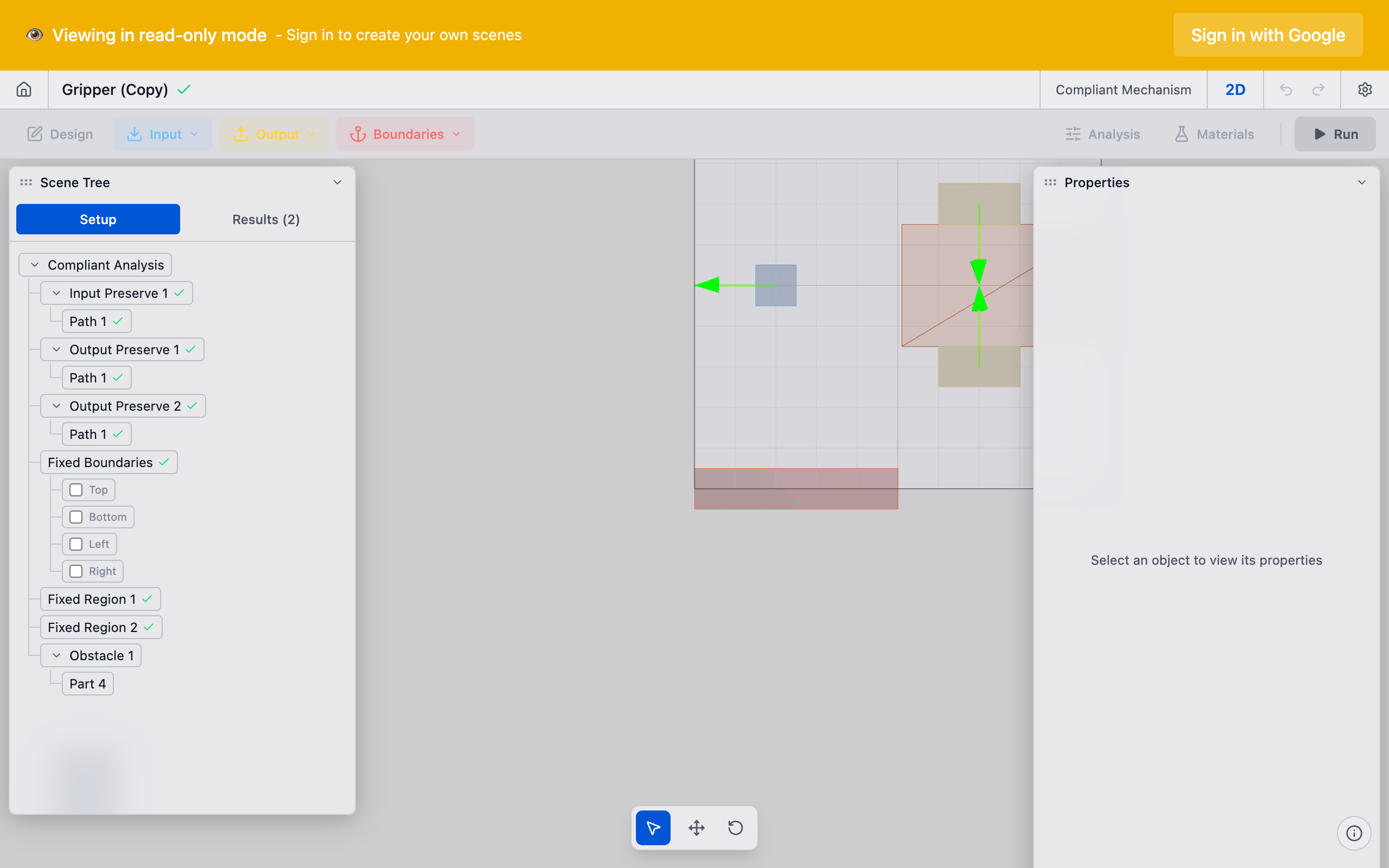
Preserves are placed on the design space canvas by clicking to position them. Each preserve type has distinct visual indicators:
- Input preserves: shown with an arrow indicating the force direction
- Output preserves: shown with an arrow indicating the desired motion direction
- Fixed preserves: shown with a ground/anchor symbol
- Bolt pads: shown as rectangular regions at mounting locations
Place preserves with mechanical reasoning in mind. Ask yourself: "Where does force enter? Where do I want motion? Where is this part bolted down?" The answers to these three questions define your preserve layout.
Sizing
Preserve size affects the optimization in two ways:
- Structural: larger preserves provide more surface area for force distribution, reducing stress concentrations
- Topological: larger preserves lock more elements to solid, reducing the optimizer's freedom
For most problems, preserves should be sized to match the physical features they represent — bolt hole diameters, mounting pad sizes, actuator contact areas. Oversized preserves waste design space. Undersized preserves create unrealistic stress concentrations.
Direction Vectors
Input and output preserves carry direction vectors that define:
- For input preserves: the direction of the applied force
- For output preserves: the direction of desired output motion
Direction vectors are 2D unit vectors. Common directions include:
- (1, 0) — positive X (rightward)
- (0, 1) — positive Y (upward)
- (-1, 0) — negative X (leftward)
- (0, -1) — negative Y (downward)
Angled directions work too — (0.707, 0.707) for a 45-degree direction, for example.
Common Preserve Patterns
Simple Force Redirector
Input on the left pushing right, output on top wanting upward motion, fixed preserves at the bottom corners. The optimizer creates a mechanism that converts horizontal input force into vertical output motion.
Motion Amplifier
Input and output on the same axis but at different positions, with fixed preserves offset to the side. The optimizer creates a lever-like topology that amplifies displacement.
Parallel Motion Generator
Multiple input preserves acting together, single output preserve. The optimizer creates a mechanism that combines multiple inputs into a single coordinated output.
Thermal Flexure
Bolt pads as inputs with thermal expansion directions, output preserve at the center. See Thermal Flexure for details on this specialized application.
Troubleshooting
"The solver produced a disconnected result"
The optimizer could not find a connected load path between input and output through the fixed preserves. Check that:
- There is enough design space between preserves
- Fixed preserves are positioned to provide useful reaction forces
- The direction vectors are not contradictory
"The result is just a straight bar"
The preserves are too close together or the design space is too constrained. The optimizer does not have room to create a complex topology. Try increasing the design space or spreading preserves further apart.
"Large gray (intermediate density) regions near preserves"
The mesh resolution may be too coarse relative to the preserve size, or the preserve is too small. Increase mesh resolution or slightly enlarge the preserve.
See Also
- Input Preserves — force application points
- Output Preserves — desired motion locations
- Fixed Preserves — anchored mounting points
- Bolt Pads — rectangular mounting location preserves
- Pairs — linking input and output preserves
- Design Space — the region where preserves live