Input Preserves
An input preserve defines a region where external force is applied to the mechanism. It is the starting point of the load path — the place where an actuator, thermal expansion, manual force, or other external load drives the mechanism. Every compliant mechanism needs at least one input preserve.
Why It Matters
The input preserve tells the solver two critical things:
- Where force enters the mechanism (the position and extent of the preserve)
- In what direction the force acts (the direction vector)
Together, these define the applied load boundary condition for the solver. The optimizer then determines how to route this force through the design space to produce the desired output motion.
How It Works
Force Application
When the solver runs, force is applied at the center application node of the input preserve in the specified direction. The force is not distributed across all nodes in the preserve — it is concentrated at the single node closest to the pad center. This means:
- The preserve region defines which elements are locked solid, but force is applied at one node
- The direction vector is a unit vector — the solver uses a nominal force magnitude internally (the absolute magnitude does not affect the topology, only the relative stiffness matters)
The absolute force magnitude does not change the optimal topology for linear problems. Whether you apply 1 N or 1000 N, the optimizer produces the same material layout. What matters is the direction and location of the force, and the relative stiffness between input and output (controlled by the pair's K_p_max).
Direction Vector
The direction vector specifies which way the force pushes. It is a 2D unit vector defined in the global coordinate system.
Common configurations:
- Horizontal push: direction = (1, 0) or (-1, 0)
- Vertical push: direction = (0, 1) or (0, -1)
- Angled push: direction = (cos(theta), sin(theta)) for any angle theta
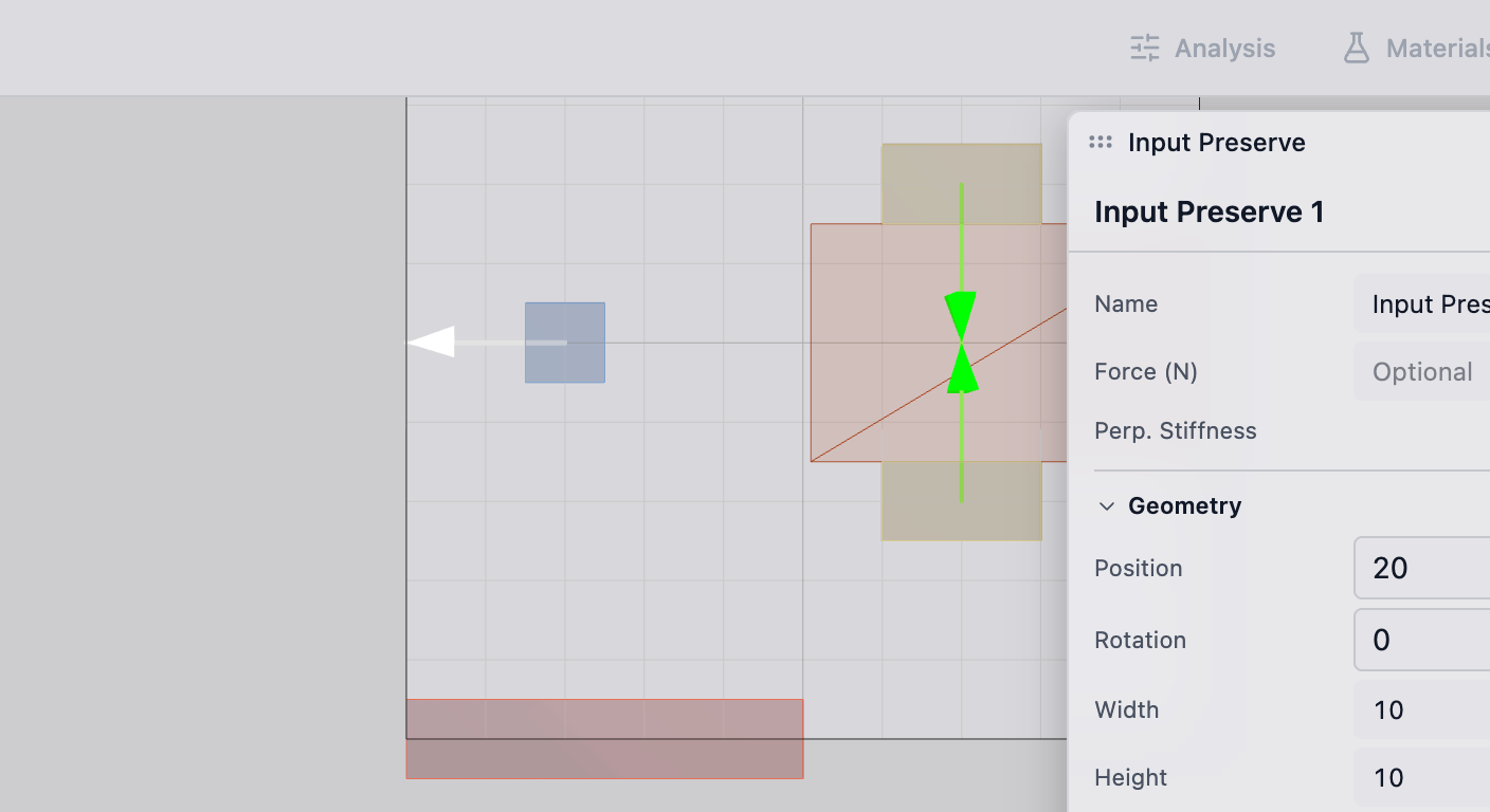
The direction is visualized as an arrow on the input preserve in the deFlex viewport.
Preserve Region
The input preserve region defines which mesh cells are locked to solid (full material) and which nodes receive force boundary conditions. The region shape depends on the source:
- Manual placement: typically a rectangular pad
- Bolt pad with input role: a rectangular region at the bolt location (see Bolt Pads)
- Imported geometry: matched to the feature geometry from the CAD model
All elements within the preserve boundary are locked to solid (full material) — the optimizer cannot remove material from an input preserve. This ensures the force application region remains physically present in the final design.
Practical Guidance
Placement
Position input preserves where the physical actuator or load source contacts the mechanism:
- Bolt hole inputs: use bolt pads with input role — force is applied at the center of the pad region
- Actuator contact: place the preserve at the actuator's contact surface
- Thermal inputs: for thermal flexure problems, place input preserves at bolt pads where thermal expansion generates displacement
The input preserve should be sized to match the real contact area. An oversized input preserve spreads force unrealistically and locks too much design space to solid. An undersized one creates stress concentrations that do not reflect the physical loading.
Multiple Inputs
A design can have multiple input preserves. Common scenarios include:
- Multiple bolt pads expanding thermally in different directions (thermal flexure)
- Redundant actuators for reliability
- Distributed loading where force enters at multiple points
Each input preserve has its own direction vector. The optimizer considers all input forces simultaneously when determining the optimal topology.
Pairing with Outputs
Input preserves must be linked to output preserves through the pair system. A pair defines:
- Which input drives which output
- The stiffness coupling between them (K_p_max)
An input preserve without a pair has no effect on the optimization objective — the solver applies the force but has no target to optimize toward. Always pair your inputs with outputs.
Technical Details
How It Works in the Solver
In the solver model, the input preserve contributes to the applied loading:
- Force is applied at the center application node in the specified direction
- The force magnitude is nominal — it does not affect the optimized design shape for linear problems
Design Update
During optimization, the solver computes how each element contributes to the objective, including the effect of the input force. Elements near the input preserve are typically important because they directly participate in the load path from the input.
Material Locking
Elements within the input preserve have their material value locked. They are not part of the design vector — they are fixed at full material. This:
- Reduces the number of design variables (slightly faster solve)
- Guarantees the input region remains solid regardless of the optimization outcome
- Creates a fixed anchor that the optimizer can reliably connect structural members to
Troubleshooting
No material connecting to the input preserve: the optimizer could not find an efficient load path from the input to the output through the available design space. Check that sufficient design space exists between the input and the nearest fixed preserve or output preserve.
Material concentrates entirely around the input: the volume fraction may be too low, or the input is too far from the output. The optimizer uses all available material on the most critical load path, which starts at the input.
Input direction does not match the physical loading: double-check the direction vector. A common mistake is specifying the reaction direction instead of the applied force direction.
See Also
- Output Preserves — the other end of the load path
- Fixed Preserves — the anchoring points
- Bolt Pads — rectangular preserves often used as inputs
- Pairs — linking inputs to outputs
- Preserves Overview — the full preserve system