Configure Volume Fraction
Use this guide to set the volume fraction for your design optimization. The volume fraction is the single most impactful parameter -- it determines what fraction of the design domain is filled with material in the final result.
What volume fraction means
A volume fraction of 0.3 means the solver can use 30% of the design domain as solid material. The remaining 70% becomes void. Lower values produce lighter, more skeletal structures. Higher values produce denser, stiffer structures.
There is no universal "correct" value. The right volume fraction depends on your application, manufacturing method, and performance requirements.
Steps
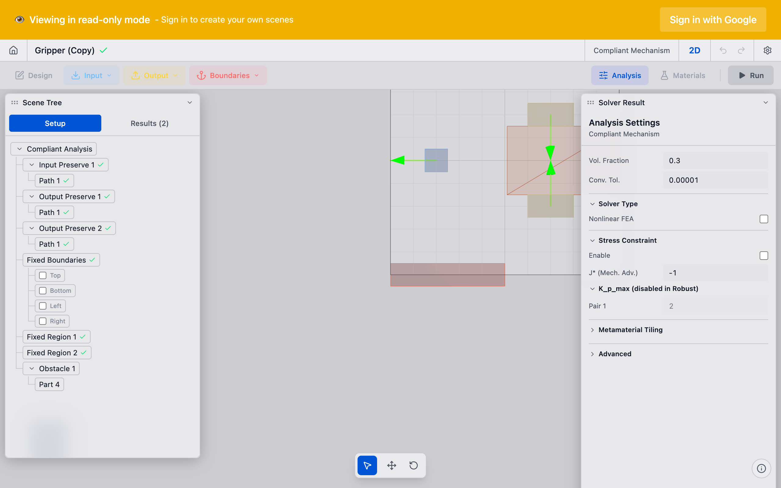
1. Open Analysis Settings
Click the Analysis button in the toolbar to open the Analysis Settings panel.
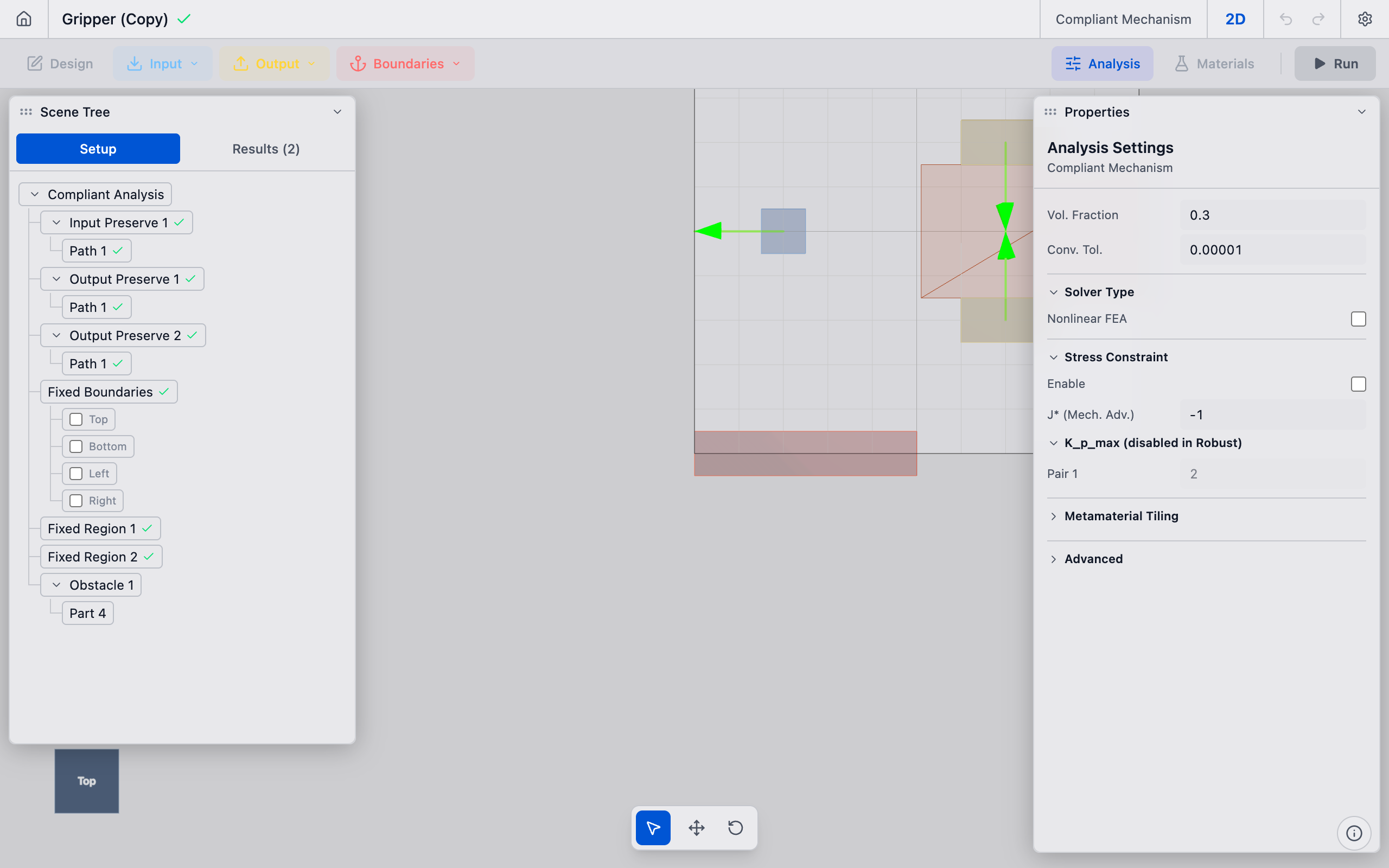
2. Set the volume fraction
The Vol. Fraction field is at the top of the panel. Enter a value between 0.05 and 0.90:
| Value | Use case |
|---|---|
| 0.10--0.20 | Very lightweight structures, where minimum weight is critical |
| 0.25--0.35 | General-purpose compliant mechanisms, good balance of flexibility and stiffness |
| 0.30 | Default value, works well for most problems |
| 0.40--0.50 | Stiffer mechanisms that need to transmit higher forces |
| 0.60--0.80 | Dense structures where stiffness dominates over weight |
The default is 0.30 (30%).

3. Consider convergence tolerance
Below the volume fraction, the Conv. Tol. field controls when the solver considers the optimization converged. The default is 0.01 (1%). Lower values (e.g., 0.001) produce more refined results but take longer. For initial exploration, the default is fine.
4. Run and evaluate
After changing the volume fraction, run the analysis. If the result has too little material and looks disconnected, increase the volume fraction. If it is too bulky, decrease it.
Guidelines for choosing volume fraction
Start at 0.30 and adjust based on results:
- Topology looks disconnected or has floating islands: Volume fraction is too low. The solver does not have enough material budget to form continuous load paths. Increase to 0.35--0.40.
- Topology looks like a solid block with small holes: Volume fraction is too high. The solver is not forced to make meaningful topology decisions. Decrease to 0.20--0.25.
- Thin flexural members break in reality: Volume fraction may be fine for topology, but the resulting members are too thin to manufacture. Increase volume fraction or increase the filter radius to enforce minimum member width.
- Solver does not converge: Extreme volume fractions (below 0.10 or above 0.80) can cause convergence difficulties. Stay in the 0.15--0.60 range for reliable results.
Tips
- Volume fraction is a constraint, not a target. The solver will use exactly the specified fraction (within tolerance). It does not "try" to use less.
- Interaction with K_p_max: For nuanced formulation mode, changing the volume fraction while keeping K_p_max constant shifts the stiffness-displacement trade-off. A lower volume fraction with the same K_p_max produces a more flexible mechanism.
- Thermal flexures: For Decoupled Thermal Flexure analyses, a volume fraction of 0.25--0.35 typically works well. The solver needs enough material to form continuous thermal paths from the bolt pads to the output region.
- Iteration speed: Volume fraction does not significantly affect computation time per iteration. The mesh resolution (element size) is the primary driver of solver speed.
What to do next
- Choose mesh resolution to set the optimization grid density
- Run the analysis to start the solver
- Interpret results to evaluate the optimized topology