Add Bolt Holes
Use this guide to define bolt hole locations on your plate. Bolt holes serve as mounting points and are central to how deFlex sets up boundary conditions -- they become input preserves (with thermal displacement directions) or fixed preserves depending on their role.
Two ways to define bolt holes
Option A: Auto-detection from STEP import
If you import a STEP file, deFlex automatically detects circular holes in the geometry and creates input preserves for each one. The bolt positions, widths, and heights are extracted from the hole geometry. This is the fastest path if you have CAD geometry with pre-placed holes.
After import, review the auto-created Bolt A, Bolt B, etc. preserves in the sidebar and adjust their properties as needed.
Option B: Manual placement
For parametric plates or when you need bolt holes that are not in the STEP geometry, add them manually.
Steps for manual bolt hole placement
1. Add an input preserve
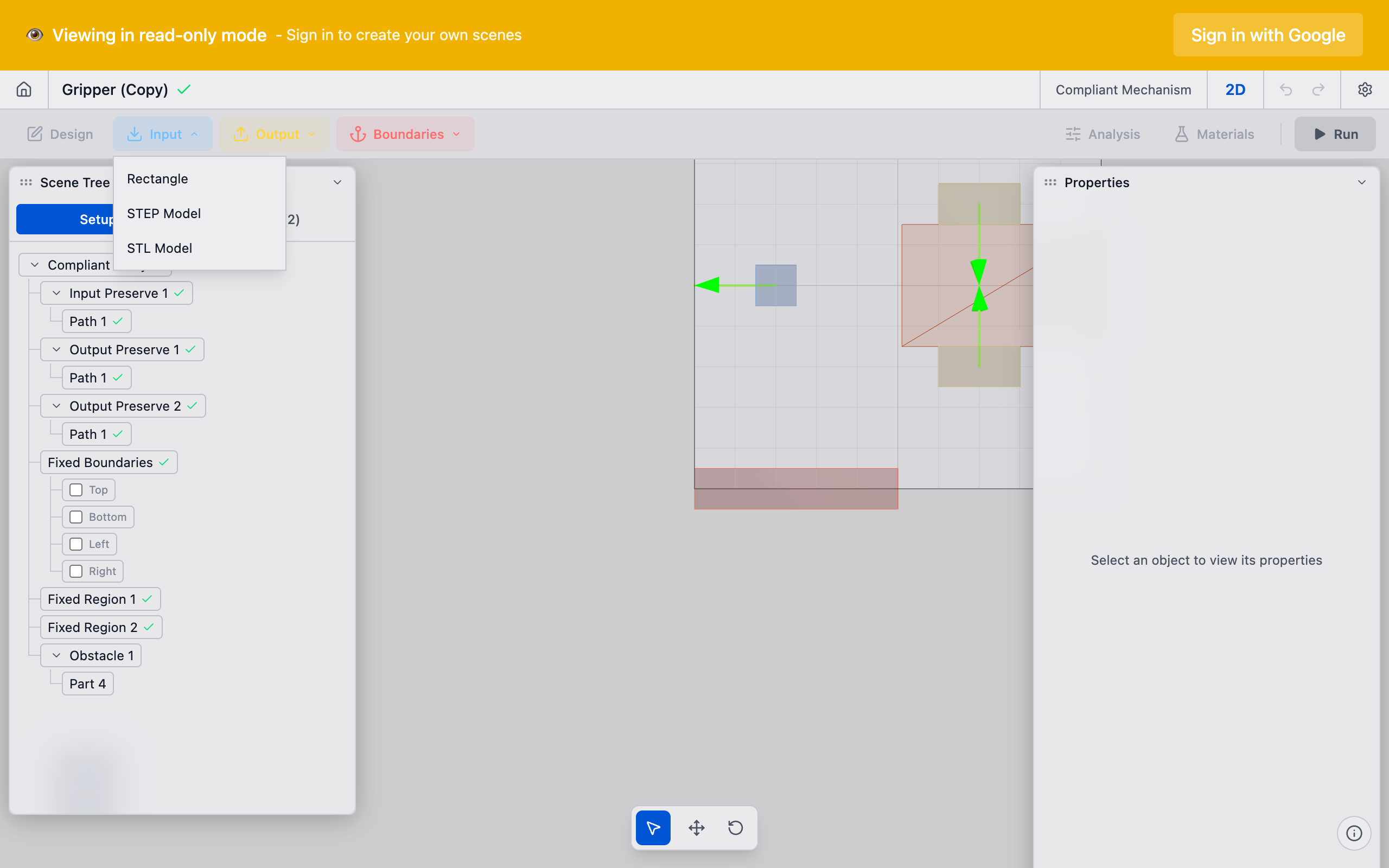
In the toolbar, click the Input dropdown and select Rectangle. A new input preserve appears in the sidebar with a default rectangular part.
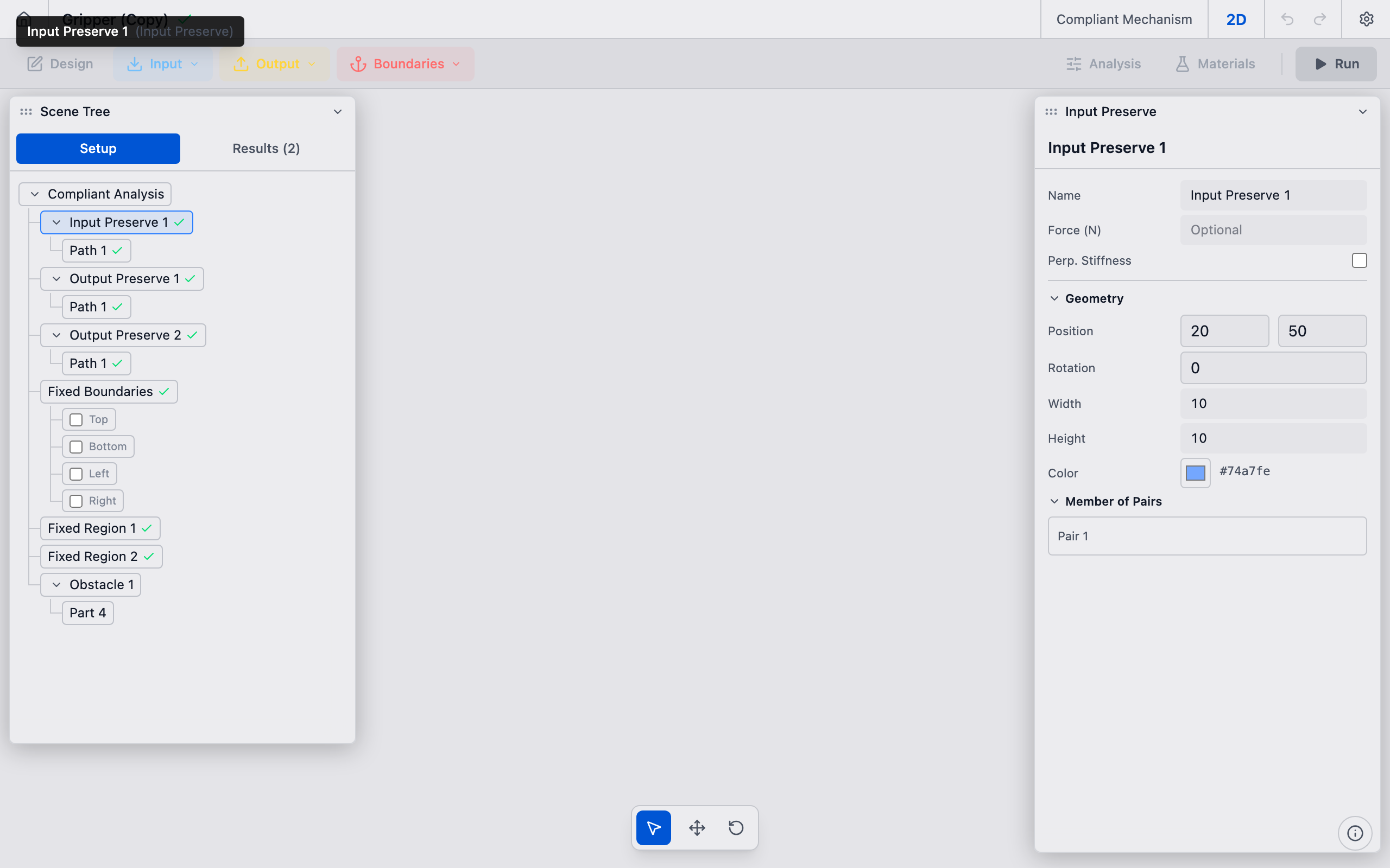
2. Position the bolt pad
Select the new preserve in the sidebar or viewport. In the Properties panel, set the part position to match your bolt hole center:
- Position X and Position Y correspond to the bolt center coordinates in millimeters.
- Width and Height define the pad extent around the hole. For a bolt on a solid plate, this represents the material annulus that transmits load -- typically 2--3x the hole diameter.
For example, for a 10 mm diameter bolt hole at position (20, 20) on a 300 x 300 mm plate, set Position X = 20, Position Y = 20, Width = 20, Height = 20.
3. Repeat for each bolt
Add additional input preserves for each bolt hole. A typical 4-bolt pattern on a 300 x 300 mm plate with holes 20 mm from the edges would have bolts at:
| Bolt | X (mm) | Y (mm) |
|---|---|---|
| A | 20 | 20 |
| B | 280 | 20 |
| C | 20 | 280 |
| D | 280 | 280 |
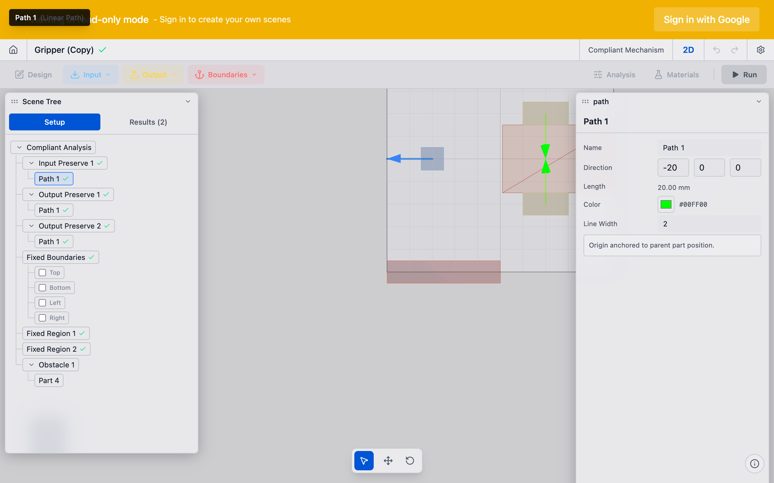
4. Set displacement directions (thermal flexure only)
For Decoupled Thermal Flexure analyses, each bolt pad needs a thermal displacement direction. This defines the direction the bolt pad moves due to thermal contraction. Select each bolt preserve and configure its path direction to match the expected thermal motion at that location.
5. Verify in the viewport
Each bolt pad appears as a colored marker in the viewport. Confirm all pads are at the correct positions and that none overlap with each other or extend beyond the design domain boundary.
Common bolt patterns
| Pattern | Bolt count | Typical use |
|---|---|---|
| 4-corner | 4 | Square/rectangular plates |
| 6-bolt | 6 | Longer rectangular plates |
| 3-bolt triangular | 3 | Circular or triangular mounts |
| Ring pattern | 8+ | Large circular flanges |
Tips
- Pad size vs. hole size: The bolt pad represents the material around the hole, not the hole itself. Make the pad larger than the actual hole diameter to capture the load transfer region.
- Edge distance: Keep bolt centers at least 1.5x the hole diameter from the plate edge to ensure adequate material for load transfer.
- Naming: Rename preserves from "Input Preserve 1" to "Bolt A", "Bolt B", etc. for clarity when you have many bolts. Right-click the preserve in the sidebar and select Rename.
- Symmetry: For symmetric problems, consider using the mirror options in Analysis Settings to reduce computation time.
What to do next
After placing bolt holes:
- Configure bolt pads with specific load or displacement properties
- Add an output preserve to define the desired mechanism output
- Add fixed preserves for mounting points that should not move